Making My Own Smart Irrigation System From Robot Scrap
Reduce, reuse, recycle!
We bought our house back in early 2020. It had some things we liked, such as a chicken coop, and some things we didn't, such as a green grass lawn. We live in the high desert (well, sort of. If you look at the map of Oregon's High Desert on Wikipedia we're just barely within the border but locally we get more precipitation than necessary to be considered desert) and water is one of those things that is a local matter of some concern. So one of the first things we did when we moved in was turn off the sprinkler system and start turning the lawn back to native ecosystem.
Shortly after turning off the lawn sprinklers, we then planted an apple orchard with 10 trees, so it's questionable whether we actually saved any water on the net, but you can't eat grass so I call it a win. If you read my post on our homemade cider press you know how much I like apples.
Apple trees planted on the border of the high desert need watering, so we buried a heavy duty hose in a small trench going out to the orchard and I connected one of those cheap battery-powered watering timers. They're about $30 each, run on two AA batteries, and connect in-line to a hose, which was great for our purposes. The batteries tend to last more than one year, which was also nice, because it meant I didn't have to worry about the batteries dying mid-season.
There were some other issues though. None of the timers we tried were terribly durable, and I found myself replacing them about every other year due to breakage. We also have a garden next to the orchard, which also needs watering but on a different schedule, so I was running two of these timers, and replacing on average one a year even though they are meant to last longer and I would disconnect them before winter. Also, they just go off at the same time every day or every other day or whatever you set; there's no way to be strategic about watering if you have a rainstorm come through. This year, I decided to fix all those problems.
What's Old is New Again
Sprinkler systems- valves, controllers, timers, etc- are surprisingly expensive. Or maybe unsurprisingly, I don't know your expectations. Remembering the old lawn sprinkler system that came with the house, I dug up the old control box and pulled out the original transformer, timer, and four solenoid valves. Why spend $300 when you can reuse what you already have? I wanted to make a whole new irrigation system that would work permanently, integrating with my smart home, buying as few new things as I could. I used to build robots (and write motion planning software) at Viam for my day job, and when that ended I was graciously allowed to keep a variety of leftover sensors, actuators, motor drivers, and other electronic bits and bobs, not to mention a few actual robots in various states of (dis)repair.
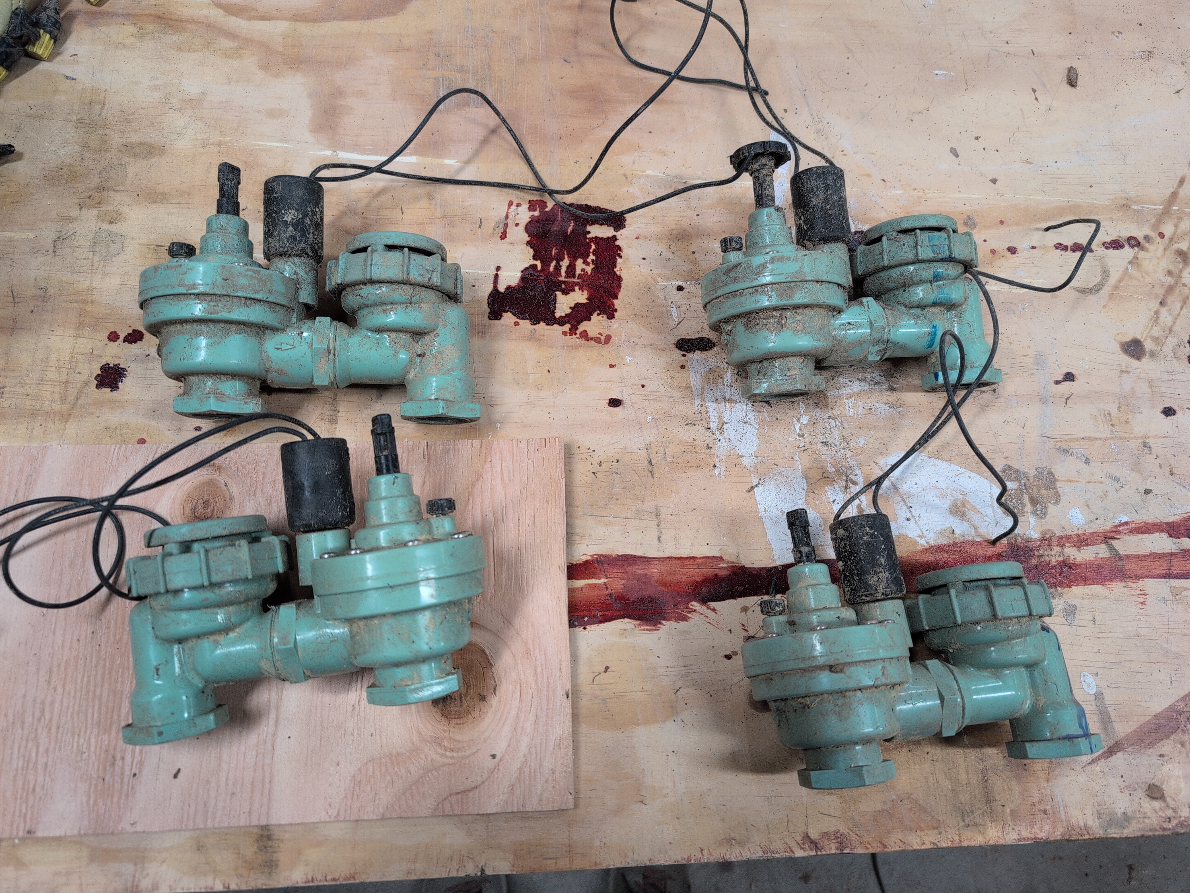
Sprinkler solenoid valves that I dug out of the ground
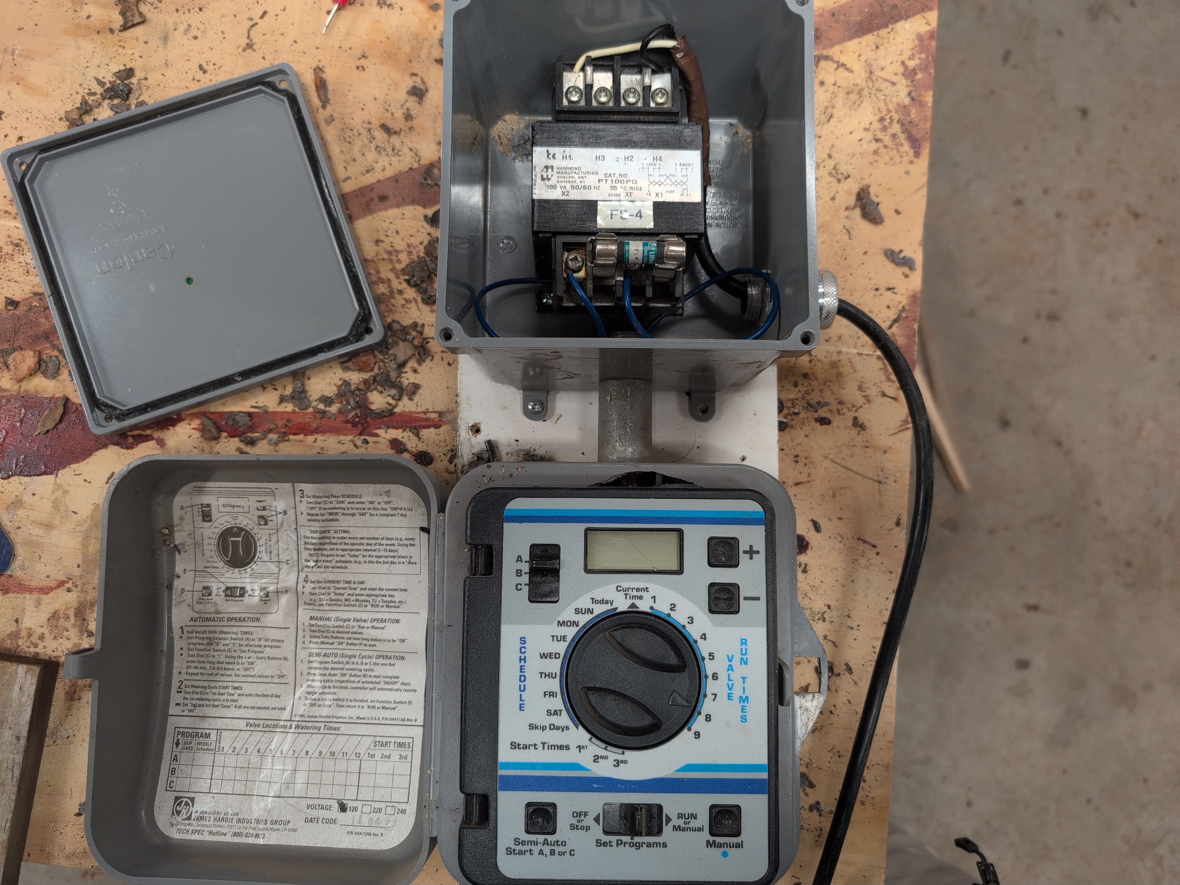
Old valve controller and transfor mer
The original system was set up with four zones controlled by the above device. Electrically, the transformer plugs into the wall, converting 120VAC to 24VAC, which is what the controller and valves run on. Based on what schedule I set, the controller will apply 24VAC to one or more solenoids, opening the associated valve and letting water through.
This control and power system poses a couple problems for me. Firstly, this is only slightly better than the battery timers mentioned above, because it doesn't allow intelligent watering based on weather conditions (whether less during rain or more during a heat wave). Secondly, the spot where I would like this to live does not have wall power available.
To solve the first problem, I'm replacing the whole watering timer assembly with a small linux computer. If you have one or many Raspberry Pis around that you thought "I'll use this for something someday", this could be that project! Personally I've been enjoying using the NanoPI Neo Air, which when I bought a stack of them were $22 each. They use almost no power (under 1 watt with wifi in use when the CPU is clocked down), and have 8gb eMMC built in, solving one of my largest complaints about the Raspberry Pi. If you're looking for a Pi alternative, that's a good place to look. I run DietPi on them. I also hear good things about the Milk-V Duo S which is a lot newer, and has a 64-bit CPU. I'll probably swap to that once my stock of Nanopis is exhausted.
I need to power things somehow, of course. I have a stack of a dozen old rooftop solar panels that I bought from a friend redoing their roof. They're old enough that the expected power return was less money than it would have cost to reinstall them, but they're still able to produce 200-odd watts each, which is way more than enough for my purposes. I have some old 48V ebike batteries, and solar battery chargers that work with 48v batteries- everything I need, hypothetically, to create an off-grid power source for irrigation and more. There are just a few problems, first and foremost that 48VDC from the batteries is neither the 24VAC needed to run the valves, nor the 120VAC needed to run the transformer to create 24VAC.
What I did have was buck converters that can convert the 48VDC to 24VDC, other buck converters able to convert 24V to 5V, and an assortment of jumper wires, H-bridges, and random components that hopefully I could pull together to make something that worked. Side note for anyone reading this and thinking "you know, I've been meaning to learn how to build electronics": as someone who self-taught all of this as an adult, building your own electronics from scratch feels like the closest thing to magic. Like actual storybook magic. You've got all this exotic stuff made of different metals and if you put them together wrong then either nothing happens or they catch fire, but do it just right- arrange those fiddly little bits in just the right way- and suddenly things work and change in the real world in exactly the way you wanted them to, because you lined up the metal bits in juuuust the right order. It feels like casting a spell, and if you think you have the time to learn about how to put stuff together like this it's absolutely a worthwhile journey. In today's world with AI it's easier than ever to get started.
The easiest thing I could do to get the needed 24VAC would be to just buy a 24V DC-to-AC inverter. Unfortunately, I didn't already have one, and 24V DC-AC inverters are obnoxiously expensive, like $100. It actually would be much cheaper to buy a cheap 120VAC inverter, and use the existing transformer. But I didn't want to do that either; that's a big extra component that I would have to buy and also comes with some fire and shock risk, etc. Better to not have it.
What I did have was a bunch of motor driver boards etc from robots. So how can I make an inverter? Well, I had a bunch of H-bridge chips, specifically the L298N. For anyone unfamiliar, these are commonly used for driving small DC motors. One feeds in some voltage, in this case 24V, and then by twiddling GPIO pins I can tell the two output terminals to be (24V, 0V) or (0V, 24V). You can probably see how this is convenient is you have a motor you want to drive forwards and backwards.
My first thought was "If I have 24VDC and I need 24VAC, and I have the ability to invert 24VDC across two terminals, can I just do that at 60hz and get what I need?" And the answer is, sort of! This was the point at which I learned a bunch of new and exciting things about AC power. If you suspect you know what I'm about to say, you can skip the next section.
A primer on AC power for people who have only used DC
The above-described idea of 24VAC power being the same as flipping 24VDC back and forth across two terminals is wrong in two important ways. The first, which I did know about beforehand (but not the implications) is that AC power is not a square wave like my H-bridge would generate; it is a sine wave. I knew this was important but I didn't know why. What I learned when checking whether this would break my solenoids or not, is that it's all about harmonics and frequencies. More simply, wall power is a wave with exactly one frequency- 60hz, or very close to it. If multiple frequencies are present, then this can cause noise and vibrations in whatever equipment is running, as you have forces going back and forth at different rates which can amplify one another or cancel each other out. As far as I could tell, it sounded like using a square wave for my AC power might cause some quiet buzzing noise from the solenoids, and potentially generate slightly more heat. Neither of which are things I particularly care about, since it will be mounted outside, with water flowing through it, and only actuating once a day at worst. I did a quick test and confirmed that the square wave will in fact open and close the solenoids.
The other way in which my preconceived notion of AC was incorrect, and this was new information to me as of this project, is that of the voltage. I had thought that 120VAC goes back and forth from +120V to -120V. Similarly that 24VAC would go back and forth between +24 and -24. But that's not true at all. AC power voltage is given in terms of the root mean squared value of the voltage- not the peak voltage. For a pure sine wave, that means the RMS value is the peak value divided by the square root of two, which means that 120VAC power coming out of your wall is actually going back and forth between +169 and -169! Fun stuff.
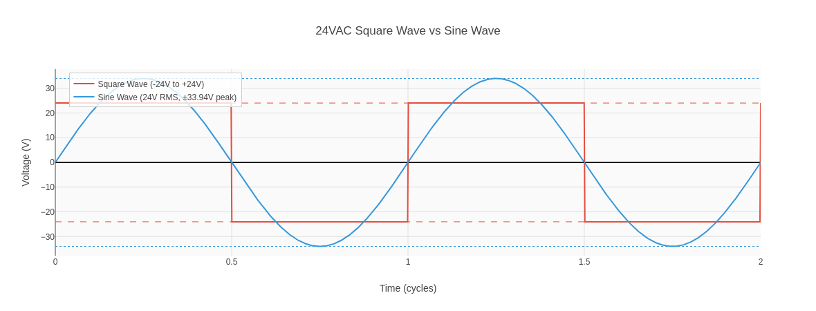
Fortunately for my homemade circuit, the RMS of a square wave is its peak. That is to say, harmonics aside, a square wave going between +24V and -24V delivers the same amount of power and has the same average voltage as a pure sine wave of 24VAC. So volumetrically, power delivery isn't an issue, and as long as the solenoid opens and closes- which it does- and doesn't burn itself out- which it hasn't yet- I think it's good enough for now. If it causes major issues, I'll probably just take that as an opportunity to learn to build my own pure sine wave inverter.
Making it go with software
With the hardware in place, I needed software to provide the needed 60hz PWM signal, easily swapped on and off remotely, and controllable based on other sensor inputs like my rain gauge and any soil moisture sensors I might decide to install. Like I mentioned earlier, I used to work for a robotics company, Viam, which makes some software that's frankly perfectly suited for this. Since I know the stack so well, having helped write a sizable chunk of it that's what I chose to do use to implement solenoid control.
Disclaimer: though I worked for Viam, this blog post is not sponsored by Viam. I executed my own idea, for fun, on my own time. Viam is not sponsoring this blog post, which I wrote entirely on my own time (while on parental leave in fact) and all opinions expressed herein are entirely my own. My choice to use a company I used to work for's software for this project stems from convenience due to me genuinely thinking it's a great tool for the job plus my own familiarity with the stack, and this is not a paid promotion.
So what's the criteria for the software that needs to exist? I needed to be able to control the solenoids, turning them on and off, based on various inputs. Those inputs would be time-based, via the weather sensor I have in HomeAssistant (and which I also wrote to run on Viam, and via any future soil moisture sensors I might decide to build. Obviously the easiest way to do all that would be to expose this as a switch in HomeAssistant. A few years ago I decided to write a HomeAssistant integration for Viam. But, there's a bug in the python SDK that will leak filehandles on long-lived client sessions (weeks to months) if the endpoint is on an unstable internet connection (for example, out in an orchard). So instead I asked Claude to write a Viam module to run the solenoid, and another to expose control of all switches and values of all sensor outputs via a REST API.
The code that actually drives the solenoid is trivial. It's a boilerplate Viam module that implements a switch, and which switched on, that switch turns on PWM on a given pin at 60hz, as well as turning on a second pin high (to turn on the H-bridge). The H-bridge needs two PWM inputs though- so I needed to turn that PWM signal into two outputs, one that matched the signal and one that inverted it. I breadboarded a NOT circuit- super simple circuit, just two resistors and a transistor- and that was all I needed for switching the solenoids on and off. I built two of these, crammed together on one breadboard, allowing me to control two solenoids.
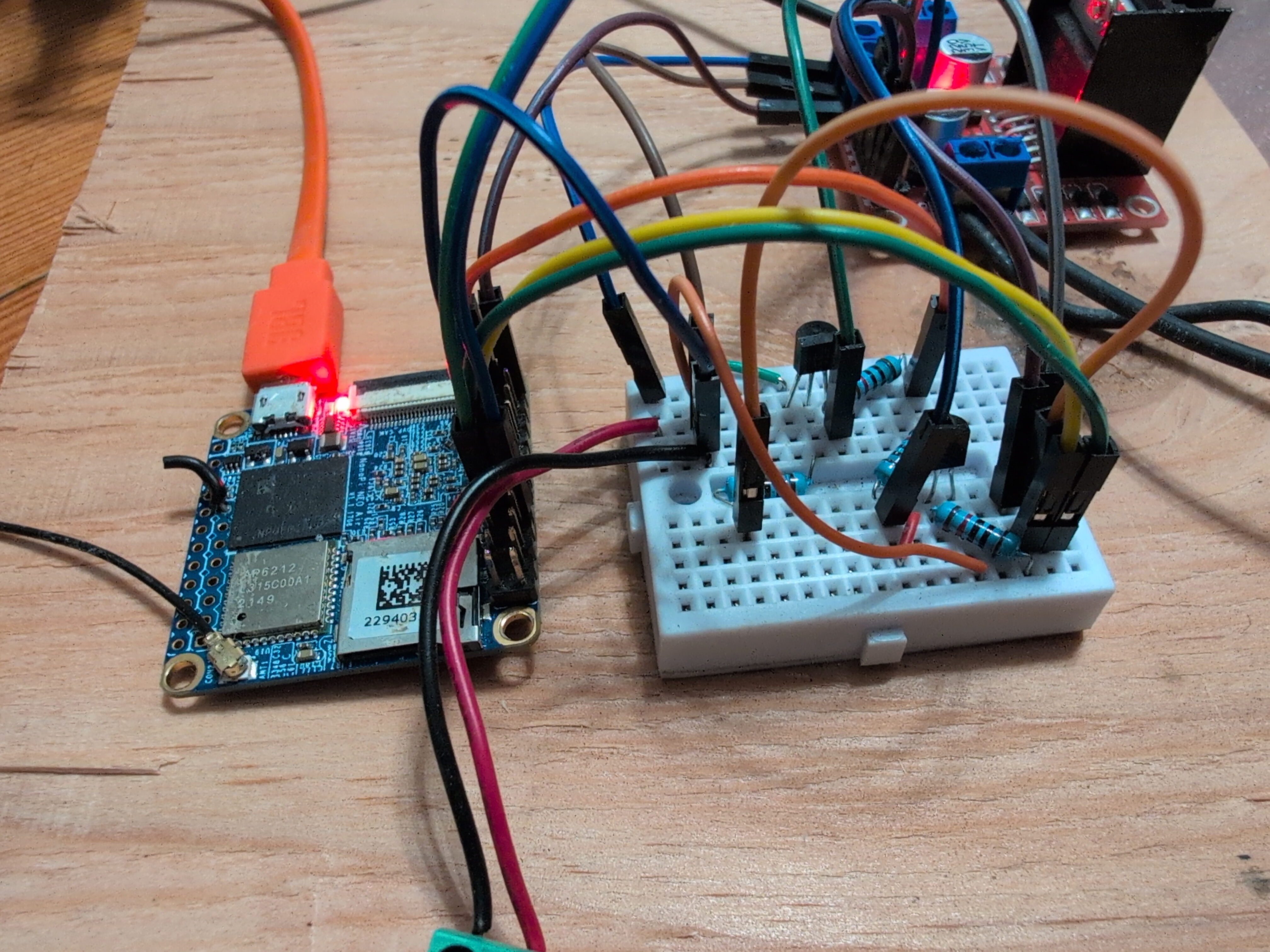
First draft of the control circuit
The eagle-eyed reader (very eagle eyed. Looking at someone else's first-draft messy breadboard and understanding anything that's going on is an impressive feat) will notice the two transistors are wired backwards from one another. This is because this project is made of scrap, and the first two loose transistors I fished out of the "surely I'll use this someday" box are different models with their pinouts opposite each other.
I then scrapped the above almost entirely. Why do I need multiple flip flop circuits? I don't. I can just have one flip flop, split the outputs across many wires, and simultaneously control arbitrarily many H-bridges. If I then twiddle the enable pins with direct GPIO, I get the same result as the first draft but with way less wires and soldering. I put this together on a perma-proto solderable breadboard, and wired the whole thing together. I updated the software so the 60hz signal is always active after init, and flipping the switch merely flips the one GPIO attached to a particular EN pin. I also added a INA219 sensor reporting power draw, which says the nanopi idles at 0.8W, jumping up to 5-10W when a solenoid is active. Here's what that final version looked like:
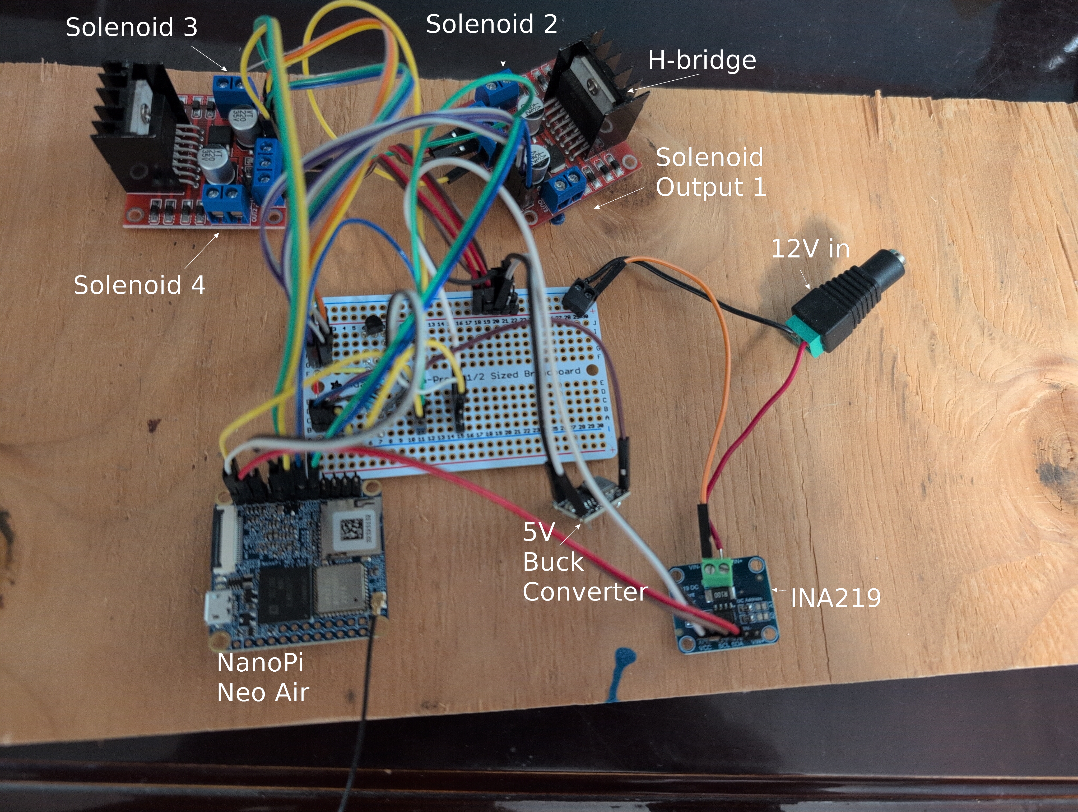
Four solenoids, four outputs on two H-bridges, perfect matchup, at least until I decide to plant more trees. Anyway, I can expand it if need be with a pipe cutter and some PVC glue, or PVC cement, whatever they call the blue goop. Three solenoids control three different orchard zones, and the last one controls the water for the chicken coop. I had a solar battery charger I got off Aliexpress for some project ages ago, and I did actually purchase a new LiFePO4 battery for the project; since the battery is living outdoors, I wanted one that would know not to charge if it were too cold.
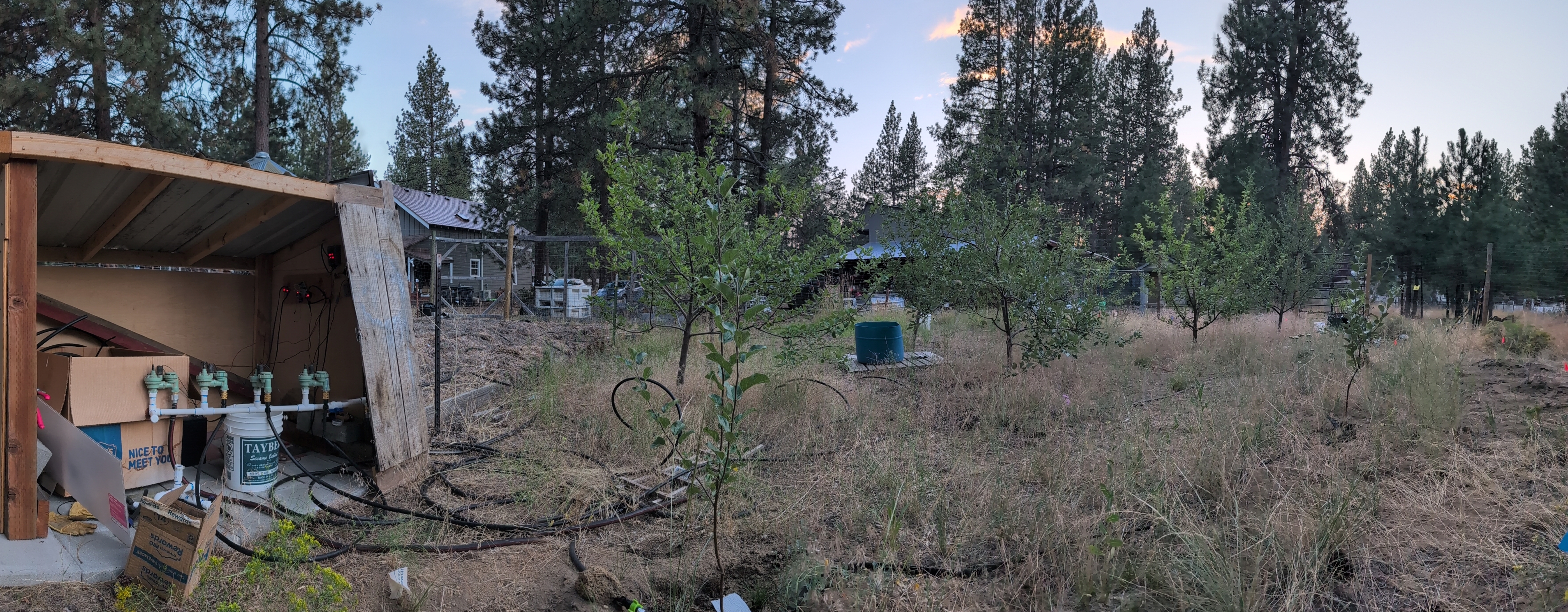
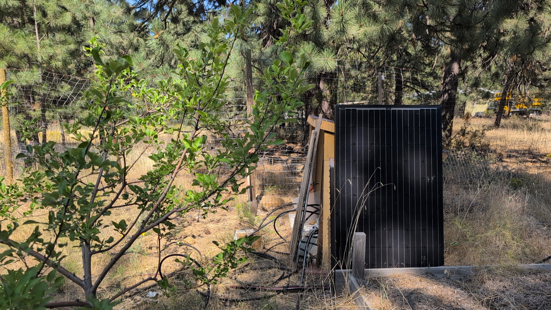
I did want at least a roof so the electronics wouldn't get wet. Fortunately, for me, we've hosted a variety of people on our property via barter; one person was a construction worker building out a bus to live in, who was happy to bring home and offer us leftovers from builds. He had left some corrugated metal roofing leaning on the side of the garage, and we have more scrap lumber than we know what to do with, so I went and had myself a good old-fashioned shed hack. I took one of the solar panels I got from my friend, a nice 320W 40V, leaned it on the shed, and bracketed it in. I figured the steep angle would shed snow in the winter, and I would have orders of magnitude more power than I needed in the summer anyway. You might have seen the whole end result in the panorama at the top of the page, but in case you didn't, here are some more photos.
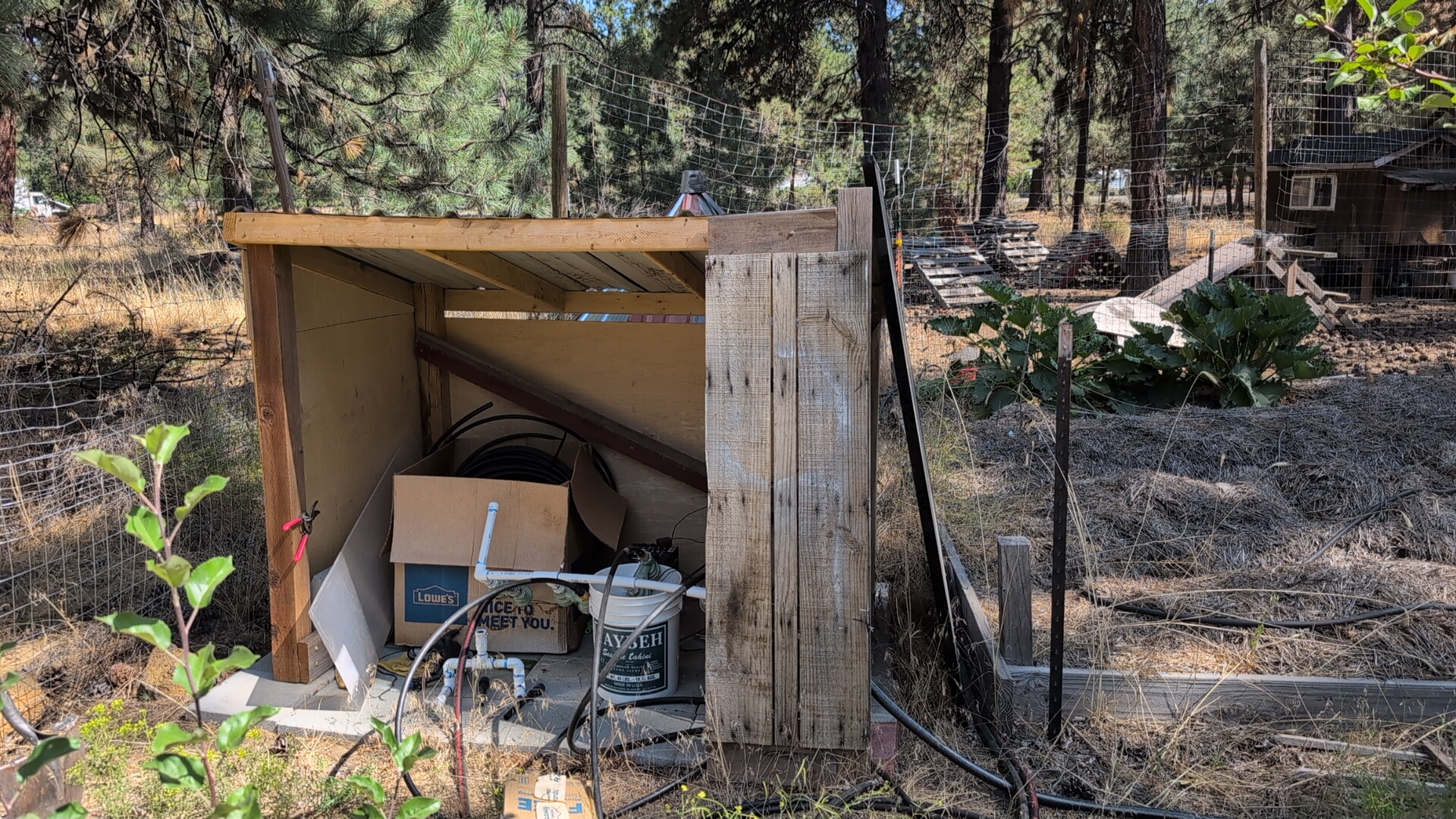
Oh and here's one more of the final circuit attached to the shed wall
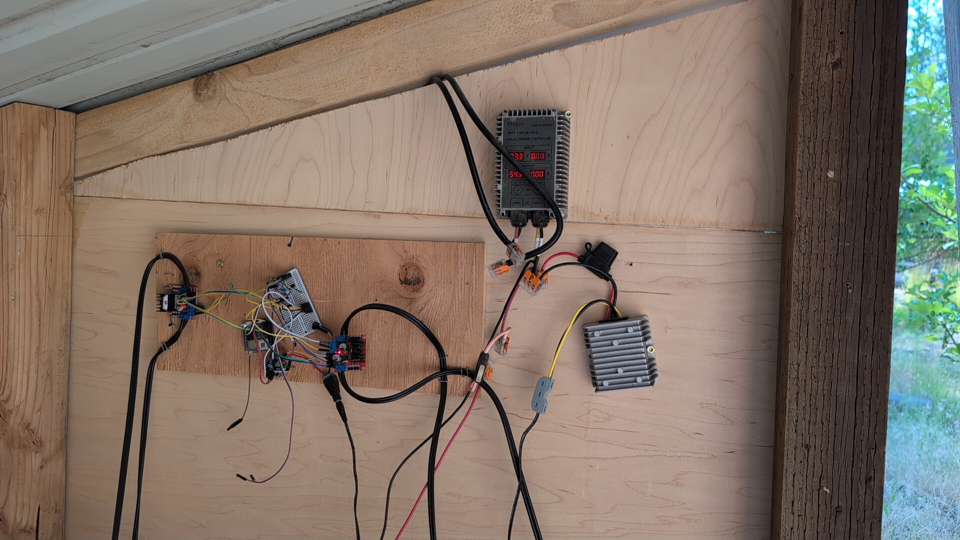
Note the fuse. It's very important to have a fuse if you DIY lithium batteries and solar. But if you didn't, I have good news: lithium batteries and solar are very good at creating their own fuses on the fly if need be
Everything worked beautifully. I was able to set up automations in Homeassistant to water when I wanted, and if it's rained more than a quarter inch in the last week, I can skip it and save some water without thinking about it. Not that the trees actually require *that* much water; a good rule of thumb for apple trees is one gallon per week per inch of trunk diameter. Three zones water 13 trees, plus I now have way better control over water for our chickens than I used to; they can now get enough water during the day, without also running the water a bunch at night.
I've got some TODOs still. I have a big stack of outdoor-rated capacitative moisture sensors, and I would love to add those into the soil as well to actually measure moisture levels so I can adjust for other conditions like drainage, humidity causing more evaporation, etc. I've been considering some sort of ultrasonic rodent deterrent to prevent gophers from eating the roots of my trees, but I'm not sure the dog would appreciate that much. But for now my trees water themselves and some of the 1-year-olds have grown several feet this season alone, and it's only August!